Building the Eun Mara "Skerry"
Ballast & trailer
I have lumped these two together because fitting the ballast was the last thing I did before loading Skerry onto the trailer.
The ballast was cast by Central Foundry in Sydney. On their recommendation we used an alloy of 98% lead and 2% antimony to provide extra hardness. I chose to cast the ballast as two ingots, mainly for ease of management. Each ingot was tapered 4 degrees on each side, again at the suggestion of the foundry. I supplied a single robust plywood template which they used for the mould.
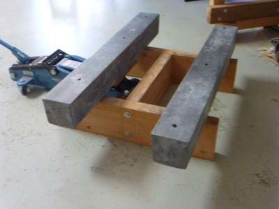
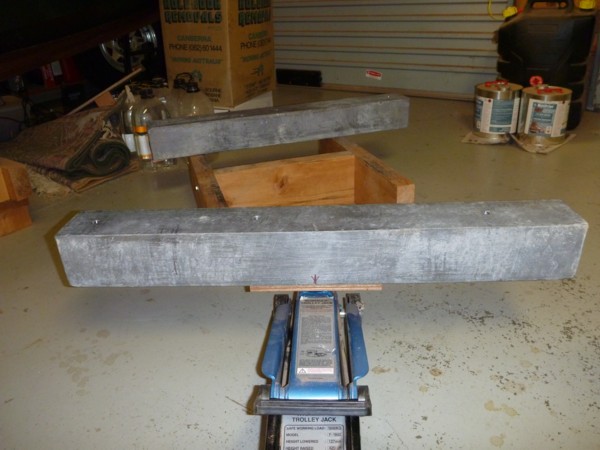
Each ingot could be lifted by two people. I made a simple timber H frame to support the ingots at a height that would allow a trolley jack to be inserted beneath them. After that I could manage an ingot on my own by marking the centre and carefully positioning the jack.
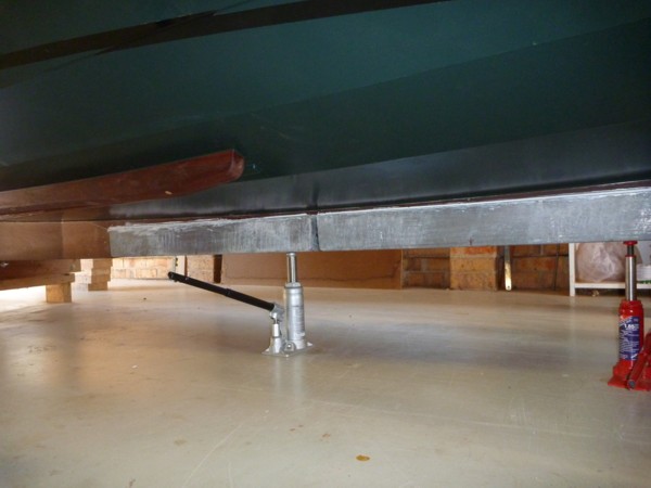
The plans specify five 12mm SS bolts for a single long ingot. I added one more support point through the keel/son so that both ingots were supported by three bolts. A liberal application of Sudbury Elastomeric Marine Sealant (white) was applied to the interface between ingots and keel. (I'd never used such a sealant before. I did the aft ingot first - hence the mess where I tried to clean up. The forward ingot is much neater!. When the sealant is fully cured I'll try to clean up the aft ingot a bit more.)
Because the timber supports are widely spaced, pending the insertion of the trailer I supported the ballast by two hydraulic jacks. Probably not necessary, but easy to do.
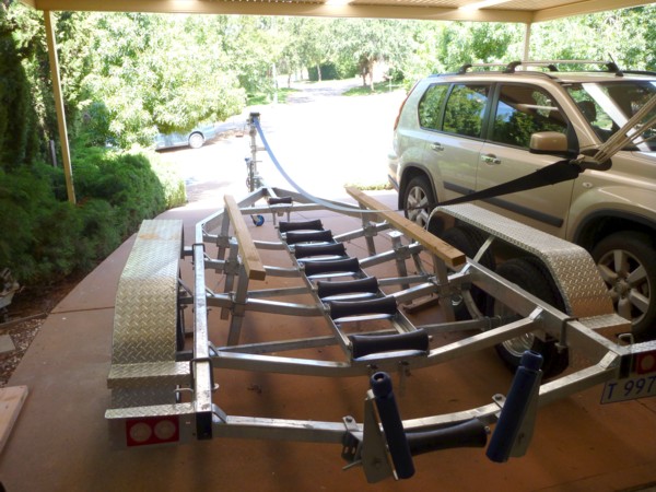
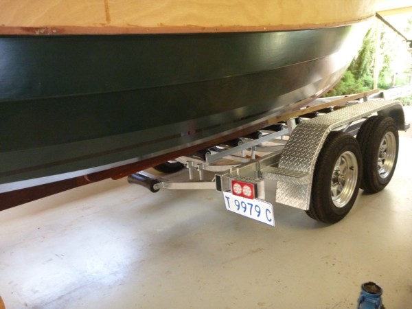
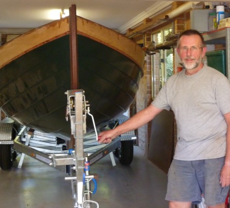
The trailer was assembled by Trailer City in Sydney. I discussed the requirements with them and chose a dual axle trailer with over-ride brakes on the front axle. There is a central "roller ladder" for the keel, and timber side-supports for the bilge runners to provide lateral stability. (The side supports shown here are temporary. In the final configuration they are 15cm wide and covered in marine grade carpet.) I chose heavy-duty steel mudguards which can safely be used for standing on, and possibly as tie-down points should that be necessary.
The next step was to load the boat (including ballast, so HEAVY) onto the trailer. I determined that the trailer would just fit into the garage if I moved my two workbenches out of the area around the back roller door. The storage shelves near the front roller door could stay in place (a bonus; I thought I would have to move them as well.)
The strategy was to keep the boat fixed, and use the trailer winch to draw the trailer under the boat. The precursor was to raise the boat by 20cm so that bottom of the keel matched (roughly) the height of the trailer rollers. We (me, Janet, and friend Matt) did this by progressively jacking up the bow and stern of the boat and inserting wooden chocks beneath the legs of the two wooden stands. It all looked a bit precarious in the end, but as Canberra is essentially earhquake free there was no real hazard!
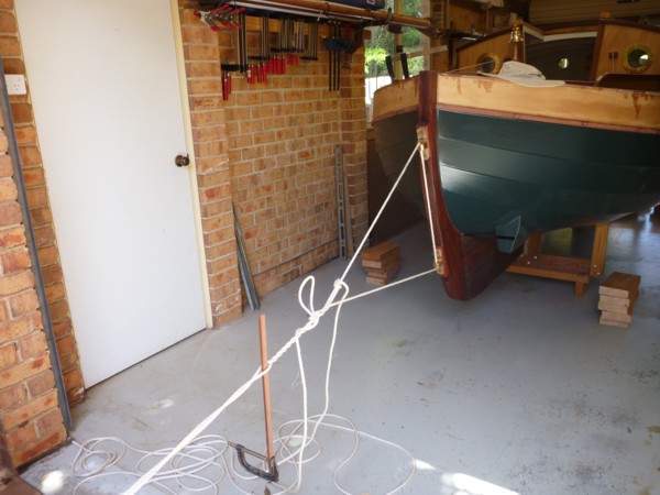
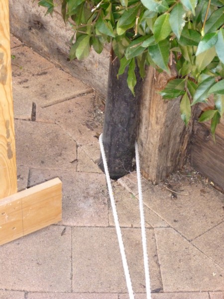
I restrained the boat from moving forward by securing the stern to a basketball post which was (by a happy coincidence) in line with the boat axis. The windlass arrangement allowed fine tuning of the tension, as the last thing I wanted was to pull over the rear stand. (You can see the piles of 5 wooden blocks on which the feet of the rear stand eventually rested. We ended up using only 4 of them.)
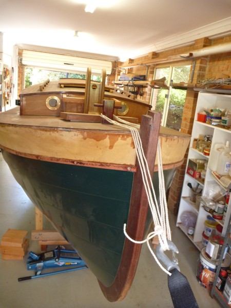
At the bow I attached a rope from the samson post to the hook on the trailer winch. (Until the boat was drawn onto the trailer it was difficult to work out where to put a permanent ring bolt through the stem.)
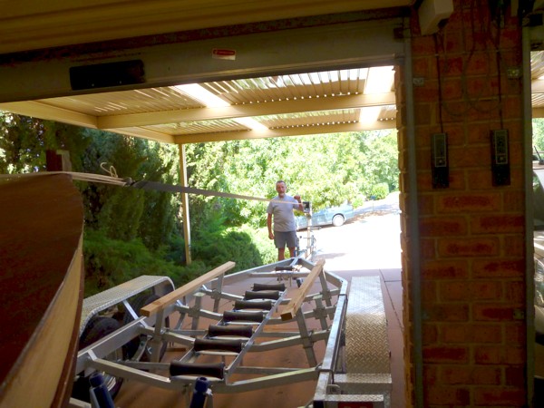
So here is the intrepid builder turning the winch handle to draw the trailer up to the stem and hoping the theory is OK! (Janet was assiduously watching the rear stand for any sign of tilting, in case there wasn't enough tension on the rear restraining rope.)
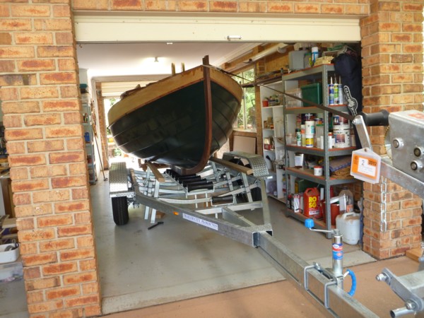
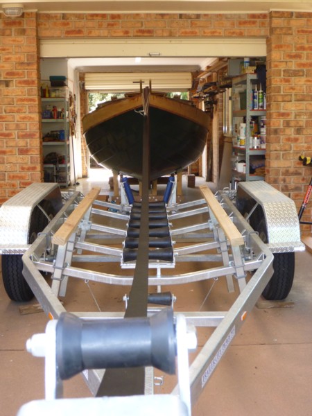
All seemed to work OK. The boat remained stationary, and in these two shots the trailer has just inserted itself under the forward end of the ballast keel and the forward stand has been removed. (Note that the blue Easy-Loader rollers visible in the previous block of photos have been removed. The springs seemed to me to be far too stiff for the plywood hull. Also, the square ends of the rollers caught under the plank lands causing the boat to rise up onto the ends of the rollers.)
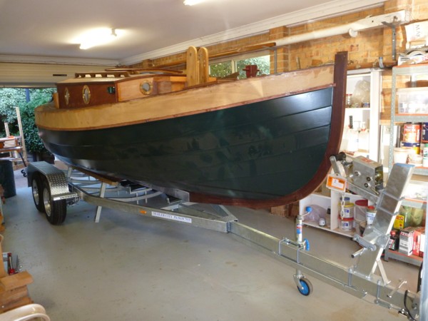
And here it is, with the trailer completely under the boat, and me looking relieved. Notice that once the boat was sufficiently far onto the trailer for me to pick the appropriate height I replaced the rope around the samson post by a ring bolt that I screwed into the stem.
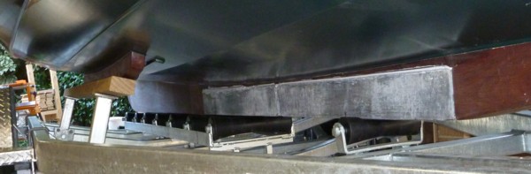
Here's a detail of how the keel sits on the rollers. I've also adjusted the side supports to match the bilge runners and bring the boat laterally horizontal.