Building the Eun Mara "Skerry"
Fitting the electric motor
Discussion
Initial work (April 2009)
Launch configuration (August 2011)
Battery bank and electrics
I liked the idea of using electric power for Skerry for several reasons:
- If I used a "pod" style motor (where everything apart from the wiring is contained in a pod slung beneath the boat) there would be no need for an outboard well, leading to a less cluttered cockpit.
- I want to use Skerry on Lake Burley Griffin (LBG) here in Canberra, where the local Traditional Boat Squadron (TBS) has regular sailing days. Unfortunately LBG is a bit small for a boat like Skerry so, for a casual day out without the hassle of rigging, using it under power would be convenient. However use of LBG by power boats is tightly regulated by the National Capital Authority (NCA). While I probably could have acquired a permit to use a petrol outboard on the basis of Skerry being a traditional design (most of the other boats in the TBS are restored or traditional looking putt-putt launches or steamboats), the NCA does not impose restrictions on electric powered boats.
- Electric power, particularly with the fully submersed pod design, is very quiet and free of fumes.
- Although a nice idea, "green" was not a selection criterion. I am fully aware that I will be charging the batteries with coal generated electricity!
Of course, one counter argument is the need for batteries. My intention at the moment is to run the motor on 36V, with six 6V flooded lead-acid batteries stowed amidships. (Probably arranged with two behind each centre case, and two in the cockpit against the cabin bulkhead.) The total battery weight would be 168Kg. (But see the eventual Battery bank and electrics.)
The motor I chose is an E-Pod 2000+ motor from Re-E-Power in the USA. It can be run at 36 or 48V. Running at 48V it is rated as being equivalent to a petrol outboard of 8 to 10 HP. As I intend running it at 36V the power will be diminished, but still more than enough to drive Skerry.
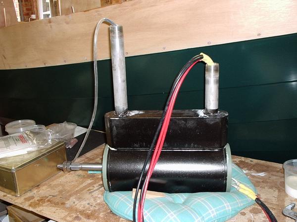
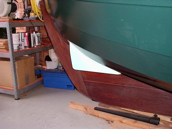
Here is the motor. It is fitted by drilling two holes through the hull, inserting the mounting pipes (which are threaded at the ends), then tightening two retaining nuts inside the hull. Of course the problem with the Eun Mara is the canoe stern - there is no convenient level surface to receive the top of the mounting block. Kevin Plank at Re-E-Power kindly customised the lengths of the mounting pipes for me.
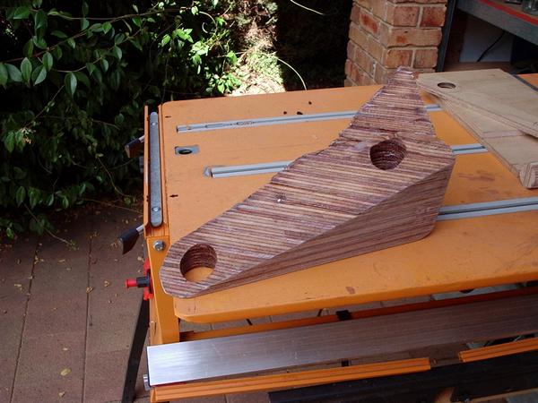
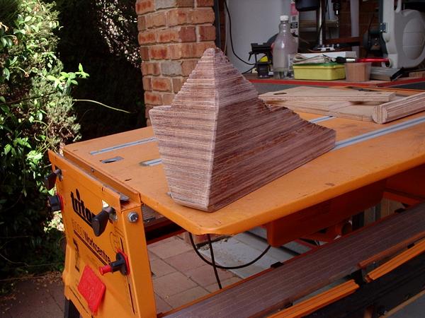
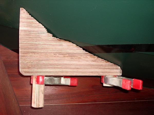
The first task was to make a mounting pylon to provide a flat surface beneath the stern on which to mount the motor. These two shots show the plywood construction. The lamination lines form interesting contours of the hull. The whole block was sealed, glassed on the sides, and then given a couple of extra coats of epoxy.
The hardest part, as always, is to drill holes in Skerry's nice hull.
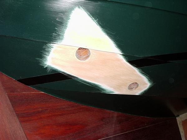
And the second hardest part is to take 40 grit sandpaper to the paintwork.
Here is the pylon dry-fitted to the hull. It's hardly a perfect fit (it crosses one of the plank lands, which made shaping it more difficult), but is adequate.
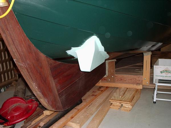
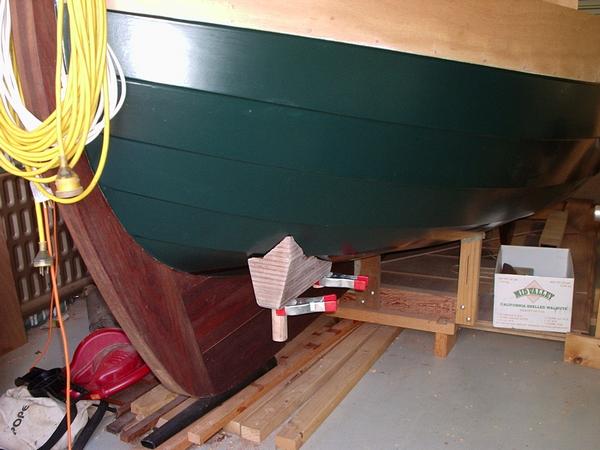
And here is the pylon epoxied in place with a couple of coats of undercoat applied.
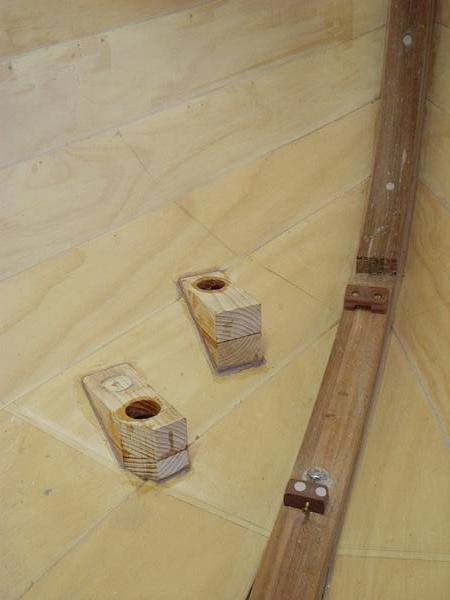
Inside the hull the reverse problem is posed. I made a couple of mounting blocks to provide a level surface on which to tighten the retaining nuts.
The motor weighs 23kg so I was concerned about stresses on the planks. The area around the closest block will be braced by the station 8 bulkhead. I have made a station 9 part-bulkhead (similar to that at station 3), which will further brace the planks aft.
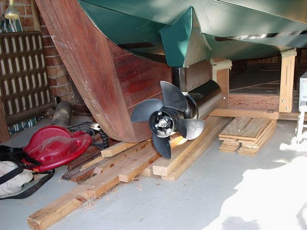
And here is the motor in place (just dry fitted for now). The bottom of the propeller is 1" above the keel - less than I would have liked, but adequate. I'll have to take care not to let the boat roll onto its starboard side if I beach it. I'll give the motor a fresh coat of black paint when it's permanently attached.
Overall the effect is a bit clunkier than I would have liked, but that's only a trailer-appeal issue. When afloat only the top of the pylon will be visible. (But see my later comment, below.)
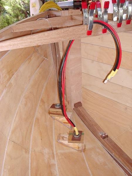
Inside the hull is simplicity itself - a couple of heavy leads to deliver all those amps to the motor, and a small poly-pipe that will allow me to check for any water in the motor casing. (Kevin at Re-E-Power assures me that there is no recorded instance of water entering the motor due to shaft seal failure. The tube has been used only to remove water that entered the motor via the inboard ends of improperly fitted mounting tubes, or was created by condensation inside the motor.)
Of course there will also be the batteries and a motor controller box, but all these should be able to be hidden discretely around the boat.
Launch configuration (August 2011)
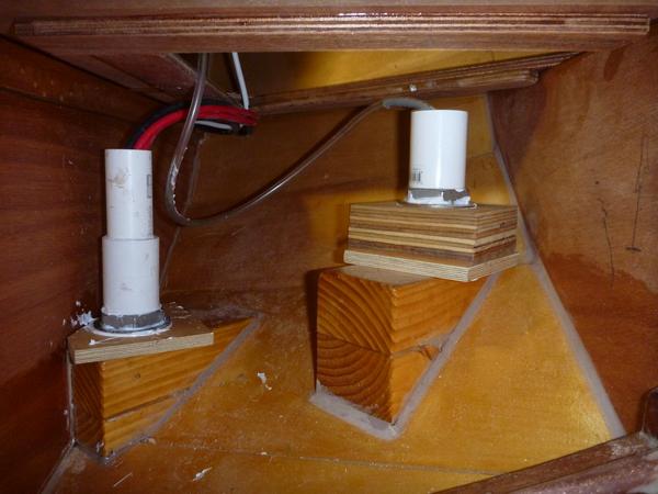
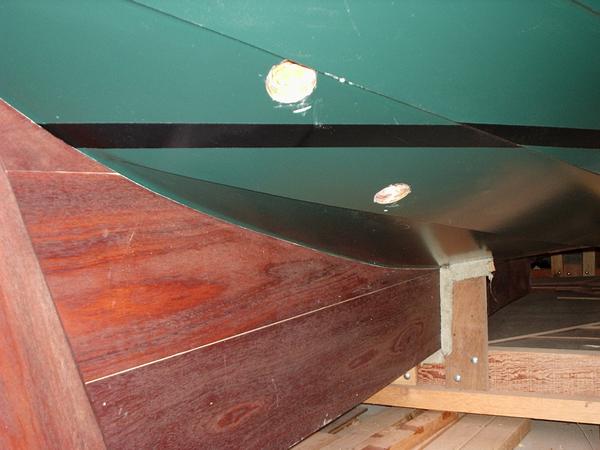
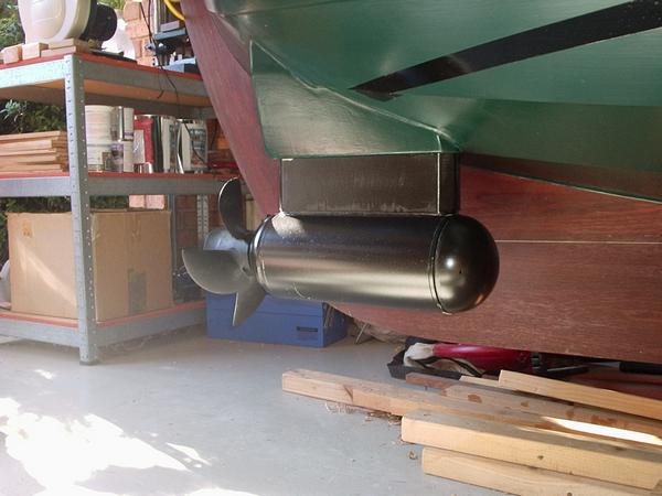
This is a close-up of the final mounting arrangement below the starboard after-deck. I extended the stainless steel mounting tubes by these plastic plumbing fittings, partly to bring the tops well above the design water-line (in case of disaster!) and partly to reduce the probability of things being dropped down the pipes and into the motor housing. I also replaced the mild steel plates, which came with the motor, with large stainless steel washers. (I believe Re-E-Power now ship SS washers with their motors).
The tube on the left side of the image takes the power cables (the black one is not very visible). The other tube has the clear plastic tube for checking for water in the motor housing. (The thin white cable is just for the cockpit lights.)
Elastomer sealant (white) has been used liberally as an extra barrier against water entry. In fact, no water should get beyond the sealant that's applied between the top of the motor mounting block and the bottom surface of the mounting pylon.
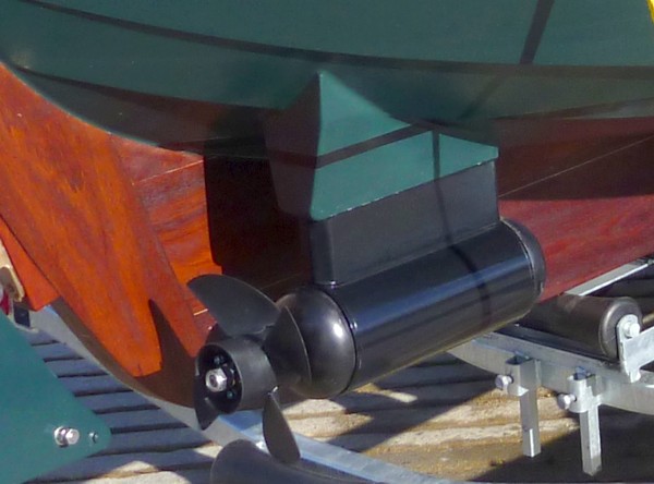
This is a good shot of the motor, taken on launch day. Contrary to my earlier opinion, in the context of the completed boat I now think it looks great, particularly with a fresh coat of black paint. It certainly generated a lot of interest during the launch.
Eventually I opted for a 48 volt system comprising eight 225AH 6V AGM batteries, total weight 270kg. I positioned them as far forward as was possible without impinging on the seating area of the cabin. Batteries, charger and customised cabling were provided by Ecoboats.
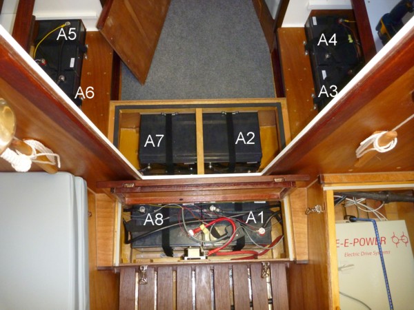
This image shows the arrangement of the batteries and motor controller (at lower right). The label A1 denotes the most negative battery, and A8 the most positive.
The following images are details of the pairs of batteries. The thin coloured wires are for the PakTrakr battery monitoring device. All batteries are sitting on sturdily mounted plywood bases. The batteries are prevented from sliding around by fiddles glued to the bases. Each battery is also restrained by Velcro straps attached to a pair of breeching staples.
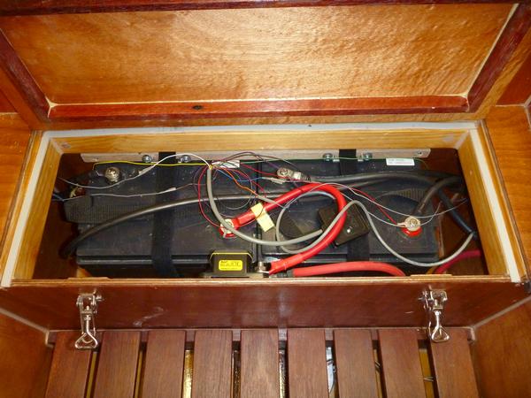
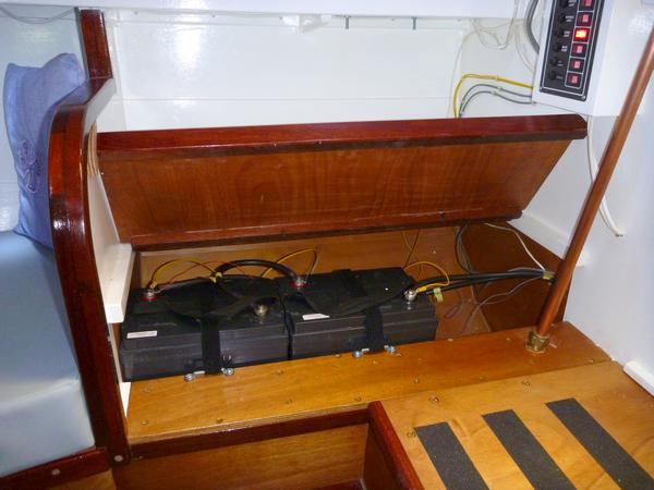
Batteries A1 (right) and A8. The small box with the yellow label is a circuit breaker/isolation switch. The small black box (partly covered by the curved red cable) is the PakTrakr controller. These batteries are mounted vertically in the locker aft of the companionway.
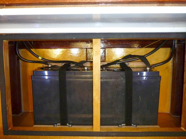
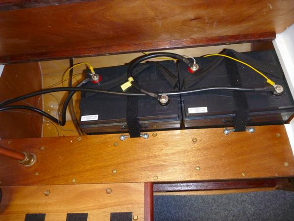
These two images show batteries A2 (left) and A7. They are mounted on their sides (this is OK with AGM batteries, as confirmed by the manufacturer) in a locker on the forward side of the companionway. The top image clearly shows the breeching staples to which the Velcro straps are attached. When the lid is in place this locker provides a convenient place to stand when the sliding hatch is open. (Because this locker obtrudes into the cabin I made the hatch opening a few inches longer than the plans indicate in order to allow headroom when stepping down onto the cabin floor.)
The remaining four batteries are mounted in pairs behind the bilgeboard cases. The top image shows A5 (right) and A6, while the other shows A3 (right) and A4. (In fact, because the cases are angled inboard at the top, the inboard edge of the base of each battery is resting on the lower rail of the case.)
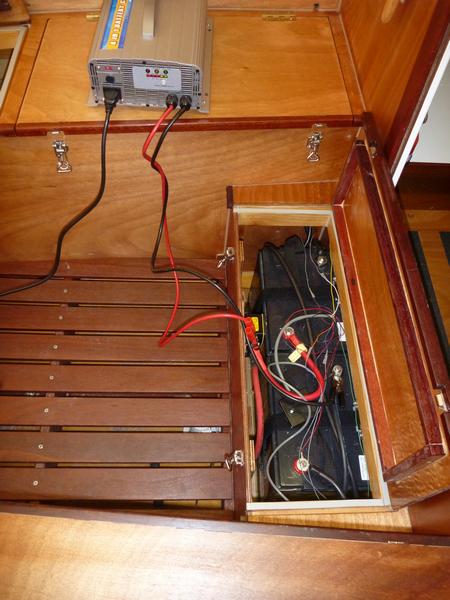
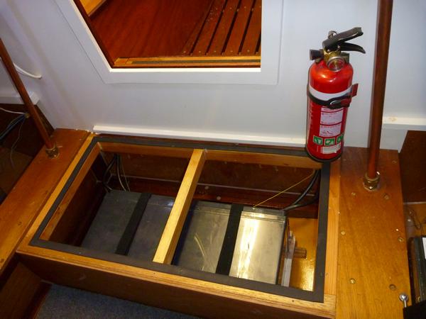
This image show the battery charging arrangement. As the charger automatically handles a bank of up to 48V, I just need to clip the positive lead to the positive terminal of battery A8 and the other lead to the negative terminal of battery A1. The isolation switch can be set to OFF for safety. The smart charger can be left continuously ON when the boat is in storage to keep the batteries optimally charged.
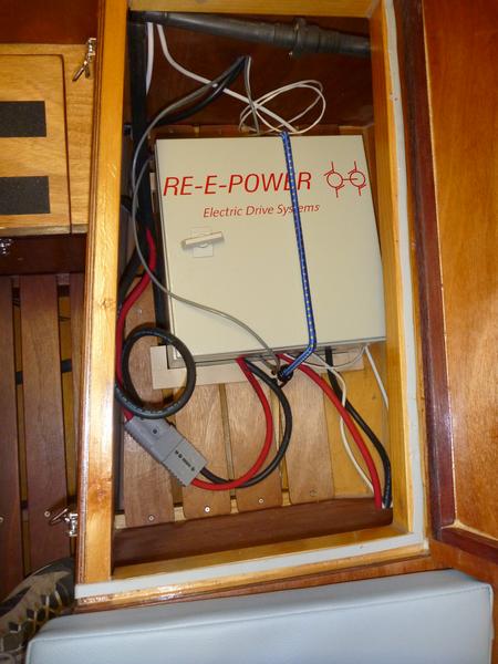
Here is the motor controller, again secured in position by fiddles around the base, and further secured by the bungee strap. The leads to the motor extend through the station 7 part bulkhead at the bottom of the image.
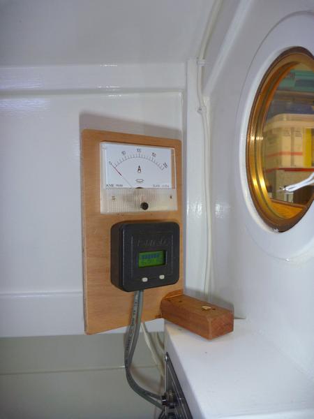
This image shows the swivelling mounting arrangement for the ammeter and PakTrakr display. This allows the ammeter, which is not weatherproof, to be viewed through the portlight. The PakTrakr does not need to be checked very often, so I'm happy to have to step into the cabin to view it.
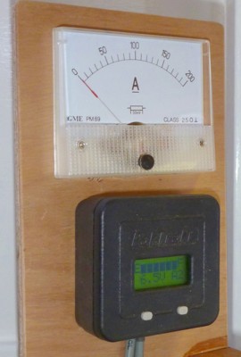
This detail shows the PakTrakr indicating full charge for the entire pack, and 6.5 volts on battery A2. Many other display modes can be selected using the two buttons.